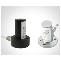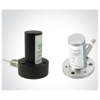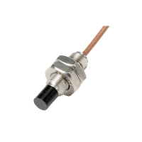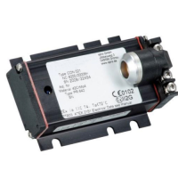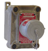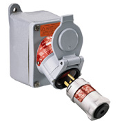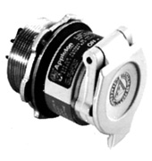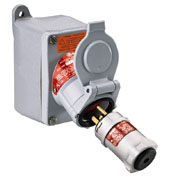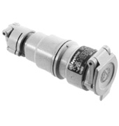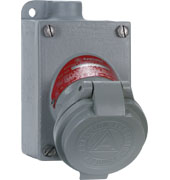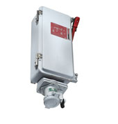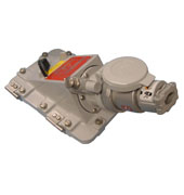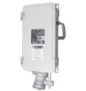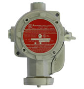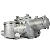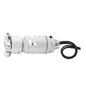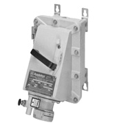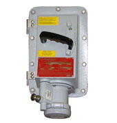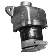
MEP Series Multi-Pin
Giá bán: Liên hệ
Hãng sản xuất: Emerson
Danh mục: Thiết bị an toàn & Phụ kiện điện tử
Nhà cung cấp: Anh Nghi Son
Xuất sứ:
Bảo hành: 12
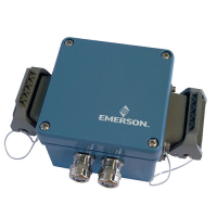
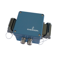
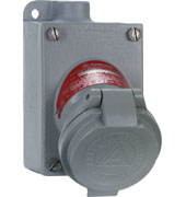
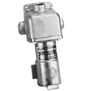
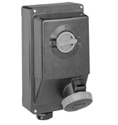
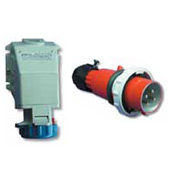
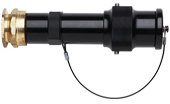
Flameproof, ATEX/IECEx certified multi-pin connectors designed for use in the toughest hazardous locations.
Multi-pin connectors are used to provide power, control, or instrumentation connection to fixed or portable equipment in hazardous environments such as process and control, marine, batch or pilot processing plants, industrial power distribution systems, transportation, back-up power and pharmaceutical manufacturing equipment.
- ATEX Cable Mount Plug and Receptacle:
– II GD Ex d IIC T6 Gb
– II GD Ex tD A21 T85˚C
– Tamb -20 °C to +40 °C
– IP68 -
ATEX Cable Mount Plug and Receptacle:
– II GD Ex d IIC T6 Gb
– II GD Ex tD A21 T85˚C
– Tamb -20 °C to +40 °C
– IP68 - IECEx:
– Ex d/de IIC T6 Gb
– Ex tb IIIC T85C Db
– Tamb -20 °C to +40 °C
MEP Series M-Line Multi-Pin Connectors Catalog Pages
Applications & Features:
Applications
- Offshore oil rigs
- Offshore production platforms
- Pharmaceutical manufacturing equipment
- Fuel storage areas
- Airport fueling pits
- Paint spray booths
- Paint storage areas
Features
- Hazardous area, environmental connector rated IP68.
- For use in Zone 1 IIC environment.
- Designed for the roughest industrial applications.
- Large coupling sleeve, secured with captive set screws.
- Secure single lead threaded coupling system.
- Durable, scratch resistant hardcoat plating.
- Vast family of reversible inserts.
- Power, signal and mixed applications.
- From 1 to 68 contact positions.
- Crimp type contacts. Solder or pressure also available.
- Contact sizes for 18, 16, 12, 10, 8, 4, 1/0, 4/0, 313 to 777 MCM
AWG. - Shell sizes 6, 8, 10, 12. Contact your local sales representative
for other shell sizes. - Extensive array of hardware and strain relief options.
- Custom cable assembly manufacture to support customer
application specifi c designs. - Silver plated contacts standard. Gold contacts optional.
- Stainless steel and brass components available upon request.
Catalog Numbers:
| MEP15-3-B06-355SN | CN-06-348SN | CN-12-352PN | CN-6306-12C | CN-5010-31E |
| MEP15-4-1006-355PN | CN-10-359PN | CN-12-352SN | CN-5006-12E | CN-6310-31C |
| MEP15-3-B10-376SN | CN-10-359SN | CN-12-384PN | CN-6306-14C | CN-5010-31E |
| MEP15-3-0008-321PN | CN-C12-353PN | CN-12-384SN | CN-5006-14E | CN-6312-16C |
| MEP13-3-B06-333SN | CN-C12-353SN | CN-10-313PN | CN-6306-15C | CN-8012-39E |
| MEP13-4-1006-355SN | CN-12-355PN | CN-10-313SN | CN-5006-15E | CN-5012-16E |
| MEP13-3-B06-334SN | CN-12-355SN | CN400420L | CN-6308-06C | CN-6312-18C |
| MEP13-3-B06-355PN | CN-06-355PN | CN410420L | CN-8008-23E | CN-5012-20E |
| MEP13-3-C08-355SN | CN-06-355SN | CN400820L | CN-5008-6E | CN-6312-20C |
| MEP13-3-B10-376PN | CN-06-334PN | CN410820L | CN-6308-08C | CN-5012-20E |
| MEP13-3-0008-321SN | CN-06-334SN | CN401020L | CN-5008-8E | CN-6312-22C |
| MEP13-3-0010-386SN | CN-08-376PN | CN411020L | CN-6308-10C | CN-5012-24E |
| MEP13-3-0008-321PN | CN-08-376SN | CN401214L | CN-5008-10E | CN-6312-24C |
| MEP17-3-B06-333PN | CN-08-381PN | CN411210L | CN-6308-12C | CN-5012-24E |
| MEP17-3-B06-334PN | CN-08-381SN | CN401220L | CN-5008-12E | CN-6312-26C |
| MEP17-3-C08-355PN | CN-10-380PN | CN401221L | CN-6308-14C | CN-5012-28E |
| CN-C10-379PN | CN-10-380SN | CN411220L | CN-5008-14E | CN-6312-28C |
| CN-C10-379SN | CN-C12-375PN | CN401620L | CN-6308-16C | CN-5012-28E |
| MOG-C12-535PN | CN-C12-375SN | CN411620L | CN-5008-16E | CN-6312-30C |
| MOG-C12-535SN | CN-10-375PN | 25ST35 | CN-6308-18C | CN-5012-32E |
| MOG-C12-777PN | CN-10-375SN | 25T35 | CN-5008-18E | CN-6312-32C |
| MOG-C12-777SN | CN-08-325PN | 40T35 | CN-6308-20C | CN-5012-32E |
| CN-06-327PN | CN-08-325SN | 50ST35 | CN-5008-20E | CN-6312-34C |
| CN-06-327SN | CN-08-312PN | 50T35 | CN-6308-22C | CN-5012-36E |
| CN-06-349PN | CN-08-312SN | 50ST35 | CN-5008-22E | CN-6312-36C |
| CN-06-349SN | CN-08-377PN | 50T35 | CN-6308-23C | CN-5012-36E |
| CN-06-314PN | CN-08-377SN | 63ST35 | CN-5008-23E | CN-6312-38C |
| CN-06-314SN | CN-08-355PN | 63T35 | CN-6310-10C | CN-5012-39E |
| CN-06-316PN | CN-08-355SN | 63ST35 | CN-8010-31E | CN-6312-39C |
| CN-06-316SN | CN-10-376PN | 63T35 | CN-5010-10E | CN-5012-39E |
| CN-06-322PN | CN-10-376SN | EPX4A30Z | CN-6310-12C | CN-W-5306N |
| CN-06-322SN | CN-10-388PN | EPX4A30Z | CN-5010-14E | CN-W-5308N |
| CN-06-333PN | CN-10-388SN | EPX4B70Z | CN-6310-14C | CN-W-5310N |
| CN-06-333SN | CN-10-332PN | MAT-6051A | CN-5010-14E | CN-W-5312N |
| CN-08-328PN | CN-10-332SN | MAT-6051B | CN-6310-16C | CN-W-5314N |
| CN-08-328SN | CN-10-387PN | MAT-6051C | CN-5010-18E | TC-CN-M309 |
| CN-06-324PN | CN-10-387SN | MAT-6050A | CN-6310-18C | TC-CN-10-20L |
| CN-06-324SN | CN-08-335PN | MAT-6050B | CN-5010-18E | TC-CN-12-20L |
| CN-06-353PN | CN-08-335SN | MAT-6050C | CN-6310-20C | TC-CN-16-20L |
| CN-06-353SN | CN-10-374PN | CN-6306-02C | CN-5010-20E | TI-10H |
| CN-08-316PN | CN-10-374SN | CN-8006-15E | CN-6310-22C | TI-12H |
| CN-08-316SN | CN-08-321PN | CN-5006-4E | CN-5010-24E | TI-16H |
| CN-08-375PN | CN-08-321SN | CN-6306-04C | CN-6310-24C | TEP-LG |
| CN-08-375SN | CN-10-350PN | CN-5006-4E | CN-5010-24E | TEP-SM |
| CN-06-310PN | CN-10-350SN | CN-6306-06C | CN-6310-26C | TES-10H |
| CN-06-310SN | CN-10-386PN | CN-5006-6E | CN-5010-28E | TES-12H |
| CN-06-354PN | CN-10-386SN | CN-6306-08C | CN-6310-28C | TES-16H |
| CN-06-354SN | CN-12-371PN | CN-5006-8E | CN-5010-28E | |
| CN-06-348PN | CN-12-371SN | CN-6306-10C | CN-6310-30C | |
| CN-14-339SN | CN-14-339PN | CN-5006-10E | CN-5010-31E |
Video Transcript:
Appleton Multi-Pin Connector Installation Video Transcript
MULTI-PIN ASSEMBLY INSTRUCTIONS
To benefit from these advantages, you’ll want to assemble the M-Line correctly.
We’re going to show you how.
Lay out all the components you’ll need, both materials and tools.
PREP THE CABLE
Cut the cable to length.
Measure the length of the cable adapter from the end to the start of the hex area.
cut and remove the cable’s outer jacket to match the cable adapater’s length as measured from the end to the hex area.
Bundle and tape the conductors together.
Slide the basket weave or mechanical clamp and retaining nut over the cable.
Lubricate the grommet and outer cable jacket with 70 percent isopropyl alcohol.
Slide the grommet onto the cable.
Then slide the cable adapter over the cable.
Slide the coupling nut onto the cable.
Remove the tape from the bundled conductors.
Strip the outer jacket of each conductor to the depth of the terminal so that the wire strands are visible through the terminal inspection port when inserted.
Make sure the conductor insulation is flush against the terminal.
Rotate the terminal to ensure that all strands are contained.
Crimp each terminal using the proper crimping tool, set to match the wire gauge.
With the terminal numbers facing away from you, slide the black outer insert into the plug or receptacle shell by aligning the polarization rib and slot.
Lubricate the inner insert with 70 percent isopropyl alcohol.
With the terminal numbers facing you, insert it into the black outer insert by aligning the polarization rib and slot.
INSERTING THE PINS
All pins should be numbered according to your project's wiring diagram
Working outward from the center, insert the terminals with the insertion tool.
Make sure that the insertion tool’s concave side is fitted against the terminal to ensure that the tool does not slide and the terminal seats properly.
Make sure that each terminal goes into the insert opening with the corresponding number.
COMPLETE THE RECEPTACLE
Once all terminals are properly seated, slide the coupling nut over the plug or receptacle shell.
Hand-tighten the cable adapter counter-clockwise.
Lubricate the cable with isopropyl alcohol and slide the grommet into the adapter.
Slide the basket weave or mechanical clamp onto the adapter.
Attach the connector to a mating assembly secured in a bench vise, which holds the interior terminals together tightly in the adapter.
Shoulder the cable adapter against the coupling nut using a strap wrench, turning counter-clockwise.
Tighten the basket weave or mechanical clamp with a strap wrench, then tighten the cable clamp screws on the mechanical clamp.
FOR PANEL MOUNT RECEPTACLES
The process you’ve just seen is identical for panel-mount receptacle assemblies. Only the physical connection method is different.
FOR HAZARDOUS LOCATIONS ONLY
Potting may be required for connectors in hazardous locations.
Appleton’s MEP series comes with important written instructions on preparing the potting material.
Be sure to consult applicable codes for installation requirements.
If potting is necessary, apply the sealing compound, manipulating the wires to ensure the compound settles.
Add material as needed to 1/16th of an inch from the opening.
Set the connector or panel mount receptacle vertically and allow 4 hours to dry.
Appleton’s complete M-Line Multi-Pin Connectors are designed for straightforward assembly and versatile, reliable performance. Consider Appleton’s M-Line for every heavy-duty and hazardous location you encounter.


